Scene Graph
1、Schematic diagram of the scene graph
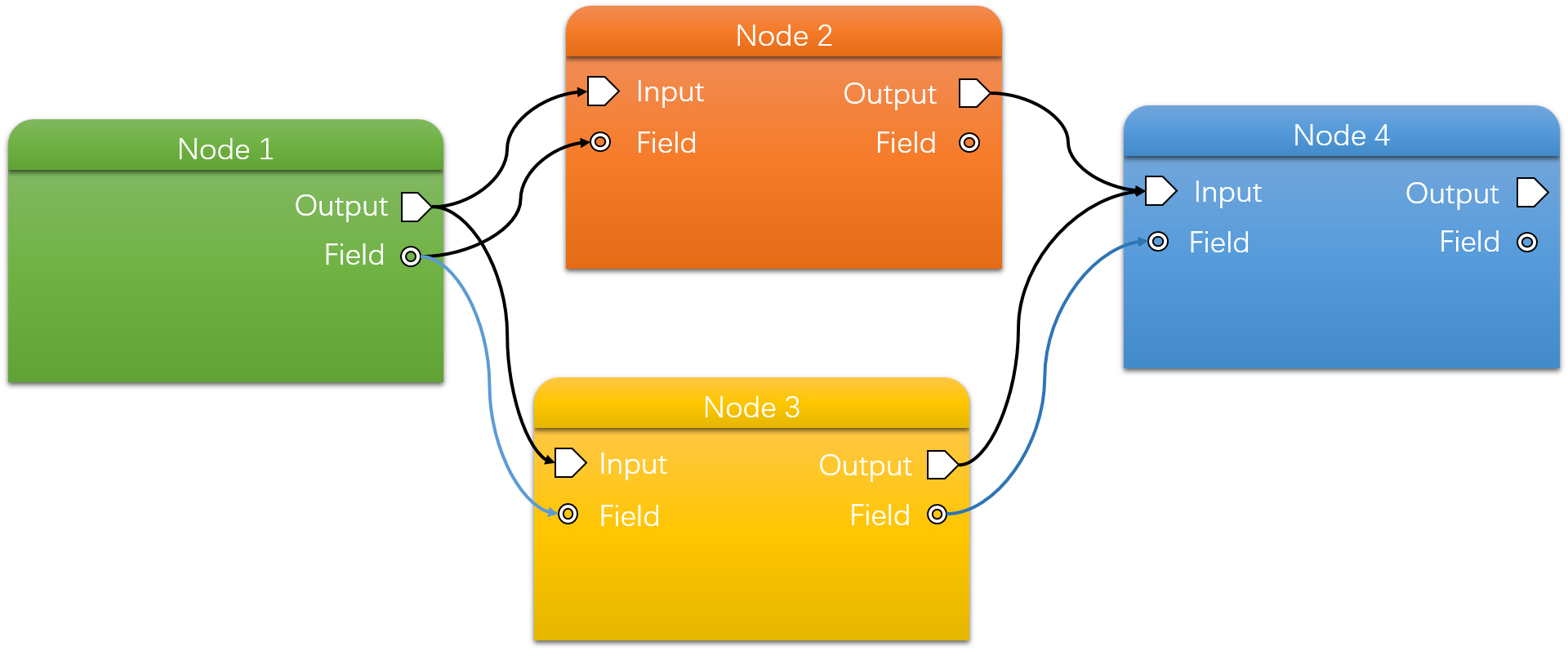
Peridyno manages all elements including Field, Module and Field in a unified manner through Scene Graph。The following figure shows a scene graph with four simulation nodes:
2、How to create a scene graph
Next, take fluid simulation as an example to show how to use peridyno to create a complete demo. The complete process consists of the following four steps:
-
Create a scene graph
std::shared_ptr<SceneGraph> scn = std::make_shared<SceneGraph>(); -
Add a simulation node
//Add a fluid simulation node auto fluid = scn->addNode(std::make_shared<ParticleFluid<DataType3f>>()); fluid->loadParticles(Vec3f(0.5, 0.2, 0.4), Vec3f(0.7, 1.5, 0.6), 0.005); //add boundary constraint Node auto boundary = scn->addNode(std::make_shared<StaticBoundary<DataType3f>>()); boundary->loadSDF(getAssetPath() + "bowl/bowl.sdf", false); //Add particle visualization node auto visualizer = scn->addNode(std::make_shared<GLPointVisualNode<DataType3f>>()); -
Set the node data connection relationship
//Fluid Node --> Boundary Constraint Node fluid->connect(boundary->importParticleSystems()); //Fluid Node --> Visualization Node fluid->connect(visualizer->importParticleSystem()); -
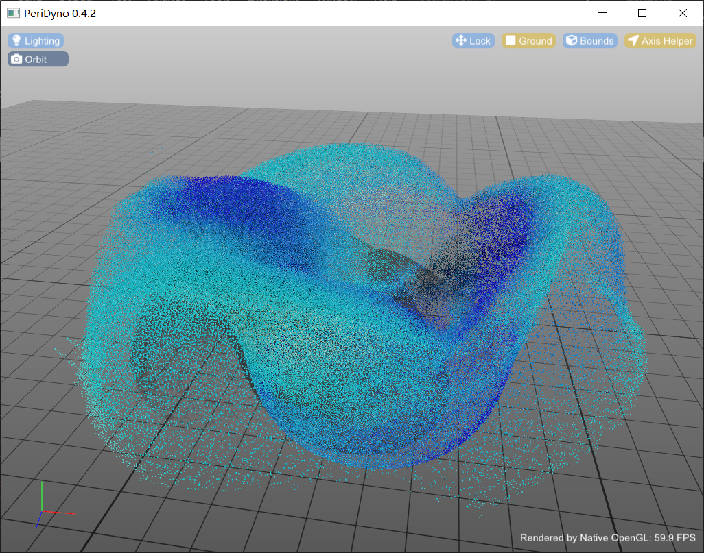
Create an application interface. PeriDyno currently supports both GLFW and QT application interfaces. Taking GLFW as an example, the algorithm flow is as follows:
GlfwApp window;

//Set up the simulation scene
window.setSceneGraph(scn);

//Create application interface
window.createWindow(1024, 768);
window.mainLoop();
The current version requires that the createWindow() function boundary must be made after the setSceneGraph() and setRenderEngine() function calls. If the rendering engine is not explicitly set, the built-in OpenGL-based GLRenderEngine is used by default.The effect diagram is as follows:
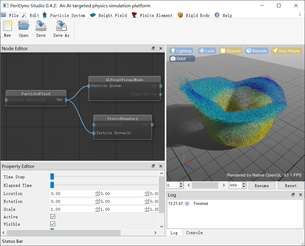
Similarly, if using the app interface:
QtApp window;

//Set up the simulation scene
window.setSceneGraph(scn);

//Create application interface
window.createWindow(1024, 768);
window.mainLoop();
对应的效果图下,做的节点编辑器展示了所有的功能节点以及节点之间的链接 关系,通过连接/断开对应的连线可以改变仿真场景图的节点执行顺序。
完整示例代码参见examples/GL_ParticleFluid和examples/Qt_GLVisualModule。